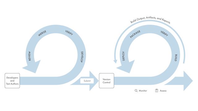
Engineering teams use Model-Based Design with MATLAB and Simulink to design complex embedded systems and generate production-quality C, C++, and HDL code. MathWorks tools use simulation testing and formal methods-based static analysis to complement Model-Based Design with rigor and automation to find errors earlier and achieve higher quality.
With MATLAB and Simulink, you can:
- Trace requirements to architecture, design, tests, and code
- Check for compliance with industry and custom modeling standards during design time
- Prove that your design meets requirements and is free of critical run-time errors
- Author test cases using test sequences and Stateflow state charts
- Collect model and code coverage to check for testing completeness
- Generate test cases automatically to analyze missing test coverage
- Produce reports and artifacts, and certify to standards (such as DO-178 and ISO 26262)
Using MATLAB and Simulink for Verification and Validation
Requirements Verification
Informal text requirements that can be stored in documents, spreadsheets, or in requirements management tools, such as IBM Rational DOORS, initiate the development process. Requirements Toolbox allows you to import, view, author, and manage requirements together with your architecture, designs, generated code, and test artifacts. You can create a digital thread from requirements to design in System Composer, Simulink, Stateflow, or tests in Simulink Test. With this traceability, you can identify implementation or testing gaps and quickly understand the impact of a change on the design or test.
You can formalize requirements and analyze them for consistency, completeness, and correctness to validate them earlier using the Requirements Table block in Requirements Toolbox. With Temporal assessments in Simulink Test, you can verify text requirements by specifying assessments with precise semantics in a natural language format that can be evaluated and debugged.
Learn More
- What Is Requirements Toolbox? (2:25)
- How to Analyze Requirements for Architectural Elements with Simulink Requirements (1:05)
- Requirements-Based Verification with Simulink Test (22:25)
- Continuous Integration: CI/CD Automation for Model-Based Design
- Agile Behavior-Driven and Test-Driven Development with Model-Based Design - White paper
Explore Products
Systematic Fault Injection and FMEA in Simulink
You can use simulation to analyze the effects of faults and other abnormal behavior to develop safety requirements and verify system robustness. Simulink Fault Analyzer enables systematic fault effect and safety analysis using simulation. The product performs fault injection simulations without modifying your design. You can manage faults modeled in Simulink, Simscape, and System Composer. Simulation Data Inspector lets you analyze fault effects. You can conduct fault sensitivity analyses using the Multiple Simulations panel. You can perform safety analyses, such as Failure Mode and Effects Analysis (FMEA), while leveraging simulation. Simulink Fault Analyzer lets you create formal connections between faults, hazards, fault detection and mitigation logic, and other artifacts (with Requirements Toolbox).
Learn More
- Simulink Fault Analyzer Essentials, Part 2: Define and Model Faults with Simulink Fault Analyzer (9:13)
- Simulink Fault Analyzer Essentials, Part 3: Create Spreadsheets in the Safety Analysis Manager (5:25)
- Simulink Fault Analyzer Essentials, Part 4: Conduct a Fault Sensitivity Study (5:23)
- Simulink Fault Analyzer Essentials, Part 5: Analyze Faults in a Fault-Tolerant Fuel System (7:53)
- Simulink Fault Analyzer Essentials, Part 6: Analyze Faults in an Aircraft Elevator Control System (9:05)
Explore Products
Certification Standards Compliance
Automate verification of models and code to standards such as DO-178, ISO 26262, IEC 61508, IEC 62304, and MathWorks Advisory Board (MAB) style guidelines. Simulink Check provides industry-recognized checks and metrics that identify standard and guideline violations during development. You can create custom checks to meet your own standards or guidelines. The IEC Certification Kit (for ISO 26262 and IEC 61508) and DO Qualification Kit (for DO-178 and DO-254) provides tool qualification artifacts, certificates, and test suites to help you qualify code generation and verification products and streamline certification of your embedded systems.
Learn More
- 11 Best Practices for Developing ISO 26262 Applications with Simulink
- Developing ISO 26262 Process Deployment
- Model Quality Objectives for Collaboration between OEM and Suppliers (24:13)
- MathWorks Advisory Board (MAB) Guidelines
- Enabling Model-Based Design for DO-254 Certification Compliance - White Paper
- How to Define Custom Edit-Time Checks (3:58)
Prove Absence of Errors and Formally Verify Requirements
Formal verification finds hidden design errors that result in integer overflow, dead logic, array access violations, and division by zero without simulating the design. Simulink Design Verifier can formally verify that your design is free from errors or security vulnerabilities. Simulink Design Verifier can also prove that your design meets critical requirements. If the tool finds an exception, it generates a counterexample for debugging.
Automatic Test Generation
It is important to identify gaps in testing, unintended functionality, or requirements errors. Simulink Coverage calculates how much of the model or generated code is exercised during testing. It applies industry standard metrics such as condition, decision, modified condition/decision (MCDC), and custom coverage objectives. Simulink Design Verifier can automatically generate test cases to address incomplete coverage to achieve structural and functional coverage objectives.
Static Code Analysis
For verification of handwritten and generated code, Polyspace products use formal methods to find bugs and prove the absence of critical run-time errors—without test cases or code execution. Polyspace Bug Finder checks and documents the compliance to standards such as MISRA, ISO 26262, IEC 61508, DO-178, and FDA regulations. You can check for software security vulnerabilities and standards such as CWE, CERT-C, ISO/IEC 17961, and others. Polyspace Code Prover performs static analysis to prove the absence of overflow, division-by-zero, out-of-bounds array access, and other run-time errors in C and C++ source code.
Explore Products

